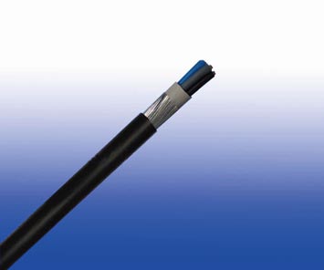
600/1000V XLPE Insulated, PVC Sheathed, Screened Power Cables (4 Cores)
FGD400 1RVCVMV-R (CU/XLPE/PVC/CUTO/PVC/SWA/PVC 600/1000V Class 2)
APPLICATION
This cables are designed specifi cally to suit the broad spectrum of requirements of Variable Speed Drives and also include features for reducing the transmission of electromagnetic interference.
This range of screened cables drastically reduce interferences from electrical noise, especially in Variable Speed Drive (VSD) applications and are manufactured with fixed conductors.With shield conductivity of 1/10th of phase conductor conductivity, this range of VSD cables effectively restrain radiated and conducted radio-frequency emissions.
STANDARDS
- Basic design adapted to IEC 60502-1
FIRE PERFORMANCE
| Flame Retardance (Single Vertical Wire Test)** |
EN 60332-1-2; IEC 60332-1-2; BS EN 60332-1-2; VDE 0482-332-1; NBN C 30-004 (cat. F1); NF C32-070-2.1(C2); CEI 20-35/1-2; EN 50265-2-1*; DIN VDE 0482-265-2-1* |
| Reduced Fire Propagation (Vertically-mounted bundled wires & cable test)** |
EN 60332-3-22 (cat. A); IEC 60332-3-22; BS EN 60332-3-22; VDE 0482-332-3; NBN C 30-004 (cat. F2); NF C32-070-2.2(C1);CEI 20-22/3-4; EN 50266-2-4*; DIN VDE 0482-266-2-4 |
Note: Asterisk ** denotes that the standard compliance is optional, depending on the oxygen index of the PVC compound and the cable design.
VOLTAGE RATING
600/1000 V
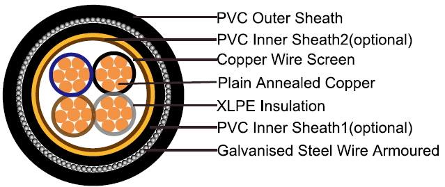
CABLE CONSTRUCTION
| Conductor |
Plain annealed copper wire, stranded according to IEC 60228 class 2 |
| Insulation |
Extruded XLPE compound |
| Inner Sheath 1 (optional) |
Thermoplastic PVC compound |
| Overall Screen |
Copper wire braiding,or copper tape with drain wire
|
| Inner Sheath 2 (optional) |
Thermoplastic PVC compound |
| Armouring |
Galvanised steel wire |
| Outer Sheath |
Thermoplastic PVC compound. UV resistance, hydrocarbon resistance, oil resistance, anti rodent and anti termite properties can be offered as option. Compliance to fire performance standard (IEC 60332-1, IEC 60332-3, UL 1581, UL 1666 etc) depends on the oxygen index of the PVC compound and the overall cable design. LSPVC can also be provided upon request |
COLOUR CODE
Insulation Colour as per BS7671
| |
With Earth Conductor |
Without Earth Conductor |
| 2Cores |
- |
Brown, Blue |
| 3Cores |
Yellow/Green, Brown, Blue |
Brown, Gray, Black |
| 4Cores |
Yellow/Green, Brown, Gray, Black |
Brown, Gray, Black, Blue |
| 5Cores |
Yellow/Green, Brown, Gray, Black, Blue |
Brown, Gray, Black, Blue, Black |
| Above 5 Cores |
Yellow/Green, Black Numbered |
Black Numbered |
Sheath Colour: Black (other colors upon request)
PHYSICAL AND THERMAL PROPERTIES
| Maximum temperature range during operation (XLPE) |
90°C |
| Maximum short circuit temperature (5 Seconds) |
250°C |
| Minimum bending radius |
12 x Overall Diameter |
CONSTRUCTION PARAMETERS
| Conductor |
FGD400 1RVCVMV-R |
| No. of Core X Cross Section |
No./Nominal Diameter of Strands |
Nominal Insulation Thickness |
Nominal Sheath Thickness |
Diameter
Under Screen |
Diameter Over Inner Sheath |
Armour
Wire Diameter |
Nominal
Overall Diameter |
Approx.
Weight |
| mm2 |
No./mm |
mm |
mm |
mm |
mm |
mm |
mm |
kg/km |
| 4x1.5 |
7/0.53 |
0.7 |
1.8 |
9.7 |
12.1 |
13.9 |
17.7 |
640 |
| 4x2.5 |
7/0.67 |
0.7 |
1.8 |
10.7 |
13.1 |
14.9 |
18.7 |
730 |
| 4x4 |
7/0.85 |
0.7 |
1.8 |
12.0 |
14.4 |
16.2 |
20.0 |
870 |
| 4x6 |
7/1.04 |
0.7 |
1.8 |
13.4 |
15.8 |
18.3 |
22.1 |
1180 |
| 4x10 |
7/1.35 |
0.7 |
1.8 |
15.6 |
18.0 |
20.5 |
24.3 |
1490 |
| 4x16 |
7/1.70 |
0.7 |
1.8 |
18.1 |
20.5 |
23.7 |
27.5 |
2070 |
| 4x25 |
7/2.14 |
0.9 |
1.8 |
22.3 |
24.1 |
27.3 |
31.1 |
2790 |
| 4x35(S) |
7/2.52 |
0.9 |
1.8 |
25.0 |
26.8 |
30.0 |
33.8 |
2940 |
| 4x50(S) |
19/1.78 |
1.0 |
2.0 |
27.8 |
29.6 |
32.8 |
37.0 |
3500 |
| 4x70(S) |
19/2.14 |
1.1 |
2.2 |
31.6 |
33.4 |
37.4 |
42.0 |
5000 |
| 4x95(S) |
19/2.52 |
1.1 |
2.3 |
35.4 |
37.2 |
41.2 |
46.0 |
6300 |
| 4x120(S) |
37/2.03 |
1.2 |
2.5 |
39.0 |
40.8 |
45.8 |
51.0 |
8200 |
| 4x150(S) |
37/2.25 |
1.4 |
2.6 |
42.0 |
43.8 |
48.8 |
54.2 |
9600 |
| 4x185(S) |
37/2.52 |
1.6 |
2.8 |
47.8 |
49.6 |
54.6 |
60.4 |
11500 |
| 4x240(S) |
61/2.25 |
1.7 |
3.0 |
54.0 |
55.8 |
60.8 |
67.0 |
14400 |
| 4x300(S) |
61/2.52 |
1.8 |
3.0 |
58.0 |
59.8 |
64.8 |
71.4 |
17200 |
(S) : Sectoral Stranded Conductors.
ELECTRICAL PROPERTIES
| Conductor Operating Temperature |
90°C |
| Ambient Temperature |
30°C |
Current-Carrying Capacities (Amp)
| Conductor cross-sectional area |
Reference Method C (clipped direct) |
Reference Method E (in free air or on a perforated cable tray, horizontal or vertical) |
Reference Method D (direct in in groud or in ducting in groud.in or around buildings) |
| 1 two-core cable*, single-phase a.c. or d.c. |
1 three-or four core cable*,three-phase a.c. |
1 two-core cable*, single-phasea.c. or d.c. |
1 three-or four core cable*,three-phase a.c. |
1 two-core cable*, single-phase a.c. or d.c. |
1 three-or fourcore cable*, three-phase a.c. |
| 1 |
2 |
3 |
4 |
5 |
6 |
7 |
| mm2 |
A |
A |
A |
A |
A |
A |
| 1.5 |
27 |
23 |
29 |
25 |
25 |
21 |
| 2.5 |
36 |
31 |
39 |
33 |
33 |
28 |
| 4 |
49 |
42 |
52 |
44 |
43 |
36 |
| 6 |
62 |
53 |
66 |
56 |
53 |
44 |
| 10 |
85 |
73 |
90 |
78 |
71 |
58 |
| 16 |
110 |
94 |
115 |
99 |
91 |
75 |
| 25 |
146 |
124 |
152 |
131 |
116 |
96 |
| 35 |
180 |
154 |
188 |
162 |
139 |
115 |
| 50 |
219 |
187 |
228 |
197 |
164 |
135 |
| 70 |
279 |
238 |
291 |
251 |
203 |
167 |
| 95 |
338 |
289 |
354 |
304 |
239 |
197 |
| 120 |
392 |
335 |
410 |
353 |
271 |
223 |
| 150 |
451 |
386 |
472 |
406 |
306 |
251 |
| 185 |
515 |
441 |
539 |
463 |
343 |
281 |
| 240 |
607 |
520 |
636 |
546 |
395 |
324 |
| 300 |
698 |
599 |
732 |
628 |
446 |
365 |
| 400 |
787 |
673 |
847 |
728 |
- |
- |
Voltage Drop (Per Amp Per Meter)
| Conductor cross-sectional area |
Two-core cables, d.c. |
Two-core cable, single-phase a.c. |
Three-or four core cable, three-phase a.c. |
| 1 |
2 |
3 |
4 |
| mm2 |
mV/A/m |
mV/A/m |
mV/A/m |
| 1.5 |
31 |
31 |
27 |
| 2.5 |
19 |
19 |
16 |
| 4 |
12 |
12 |
10 |
| 6 |
7.9 |
7.9 |
6.8 |
| 10 |
4.7 |
4.7 |
4.0 |
| 16 |
2.9 |
2.9 |
2.5 |
| |
|
r |
x |
z |
r |
x |
z |
| 25 |
1.85 |
1.85 |
0.160 |
1.90 |
1.60 |
0.140 |
1.65 |
| 35 |
1.35 |
1.35 |
0.155 |
1.35 |
1.15 |
0.135 |
1.15 |
| 50 |
0.98 |
0.99 |
0.155 |
1.00 |
0.86 |
0.135 |
0.87 |
| 70 |
0.67 |
0.67 |
0.150 |
0.69 |
0.59 |
0.130 |
0.60 |
| 95 |
0.49 |
0.50 |
0.150 |
0.52 |
0.43 |
0.130 |
0.45 |
| 120 |
0.39 |
0.40 |
0.145 |
0.42 |
0.34 |
0.130 |
0.37 |
| 150 |
0.31 |
0.32 |
0.145 |
0.35 |
0.38 |
0.125 |
0.30 |
| 185 |
0.25 |
0.26 |
0.145 |
0.29 |
0.22 |
0.125 |
0.26 |
| 240 |
0.195 |
0.200 |
0.140 |
0.24 |
0.175 |
0.125 |
0.21 |
| 300 |
0.155 |
0.160 |
0.140 |
0.21 |
0.140 |
0.120 |
0.185 |
| 400 |
0.120 |
0.130 |
0.140 |
0.190 |
0.115 |
0.120 |
0.165 |
Note: *Spacings larger than one cable diameter will result in a large voltage drop.
r = conductor resistance at operating temperature
x = reactance
z = impedance