600/1000V Mica+XLPE Insulated, LSZH Sheathed, Armoured Power Cables to BS 6724 (Single Core)
FFX300 1mRZ1MAZ1-R (CU/MGT+XLPE/LSZH/AWA/LSZH 600/1000V Class 2)
APPLICATION
The cables are mainly used in power stations, mass transit underground passenger systems, airports, petrochemical plants, hotels, hospitals and high-rise buildings.
STANDARDS
Basic design adapted from BS 6724
FIRE PERFORMANCE
| Circuit Integrity | IEC 60331-21; EN 6387; BS 8491 |
| Flame Retardance (Single vertical wire or cable test) | IEC 60332-1-2; EN 60332-1-2 |
| Reduced fire Propagation (Vertically-mounted bundled wires & cables test) | IEC 60332-3-24; EN 60332-3-24 |
| Halogen Free | IEC 60754-1; EN 50267-2-1 |
| No Corrosive Gas Emission | IEC 60754-2; EN 50267-2-2 |
| Minimum Smoke Emission | IEC 61034-2; EN 61034-2 |
VOLTAGE RATING
600/1000V
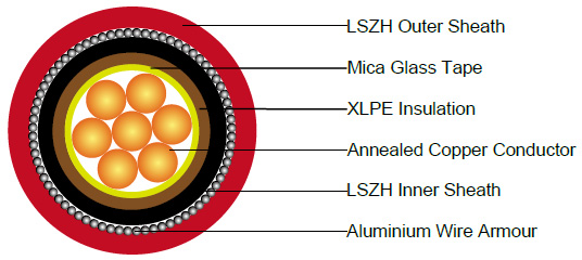
CABLE CONSTRUCTION
Conductor : Annealed copper wire, stranded according to BS EN 60228 class 2.
Fire Barrier : Mica glass tape.
Insulation : XLPE type GP 8 according to BS 7655-1.3. HEPR type GP 6 according to BS 7655-1.2 or crosslinked polyolefin material type EI 5 according to BS EN 50363-5 can be offered as option.
Bedding : Extruded layer of polymeric material.
Armouring : Aluminium wire.
Outer Sheath : Extruded layer of polymeric material LTS 1 according to BS 7655-6.1.
Outer Sheath Option : UV resistance, hydrocarbon resistance, oil resistance, anti-rodent and anti-termite properties can be offered as option.
COLOUR CODE
Insulation Colour : Brown or blue; other colours can be offered upon request.
Sheath Colour : Black; other colours can be offered upon request.
PHYSICAL AND THERMAL PROPERTIES
Maximum temperature range during operation : 90°C
Maximum short circuit temperature (5 Seconds) : 250°C
Minimum bending radius : 6 × Overall Diameter
CONSTRUCTION PARAMETERS
| Conductor | FFX300 1mRZ1MAZ1-R | ||||||
|---|---|---|---|---|---|---|---|
| No. of Cores × Cross-sectional Area | Conductor Class | Nominal Insulation Thickness | Nominal Bedding Thickness | Nominal AL Wire Armour Diameter | Nominal Sheath Thickness | Approx. Overall Diameter | Approx. Weight |
| no.×mm² | mm | mm | mm | mm | kg/km | ||
| 1×50 | 2 | 1.0 | 0.8 | 0.9 | 1.5 | 18.5 | 696 |
| 1×70 | 2 | 1.1 | 0.8 | 1.25 | 1.5 | 21.2 | 949 |
| 1×95 | 2 | 1.1 | 0.8 | 1.25 | 1.6 | 23.3 | 1253 |
| 1×120 | 2 | 1.2 | 0.8 | 1.25 | 1.6 | 25.2 | 1533 |
| 1×150 | 2 | 1.4 | 1.0 | 1.6 | 1.7 | 28.4 | 1863 |
| 1×185 | 2 | 1.6 | 1.0 | 1.6 | 1.8 | 31.0 | 2304 |
| 1×240 | 2 | 1.7 | 1.0 | 1.6 | 1.8 | 33.8 | 2938 |
| 1×300 | 2 | 1.8 | 1.0 | 1.6 | 1.9 | 36.6 | 3626 |
| 1×400 | 2 | 2.0 | 1.2 | 2.0 | 2.0 | 41.5 | 4668 |
| 1×500 | 2 | 2.2 | 1.2 | 2.0 | 2.1 | 45.2 | 5795 |
| 1×630 | 2 | 2.4 | 1.2 | 2.0 | 2.2 | 49.8 | 7357 |
| 1×800 | 2 | 2.6 | 1.4 | 2.5 | 2.4 | 56.4 | 9380 |
| 1×1000 | 2 | 2.8 | 1.4 | 2.5 | 2.5 | 61.6 | 11660 |
ELECTRICAL PROPERTIES
Conductor operating temperature : 90°C
Ambient temperature : 30°C
Current-Carrying Capacities (Amp) according to BS 7671:2008 table 4E3A
| Conductor cross-sectional area | Ref. Method C (clipped direct) | Ref. Method F (in free air or on a perforated cable tray, horizontal or vertical) | |||||||||
|---|---|---|---|---|---|---|---|---|---|---|---|
| Touching | Touching | Spaced by on cable diameter | |||||||||
| 2 cables, single-phase a.c. or d.c. flat | 3 or 4 cables, three-phase a.c. flat | 2 cables, single-phase a.c. or d.c. flat | 3 or 4 cables, three-phase a.c. flat | 3 cables three-phase a.c. trefoil | 2 cables, d.c. | 2 cables, single-phase a.c. | 3 or 4 cables, three-phase a.c. | ||||
| Horizontal | Vertical | Horizontal | Vertical | Horizontal | Vertical | ||||||
| 1 | 2 | 3 | 4 | 5 | 6 | 7 | 8 | 9 | 10 | 11 | 12 |
| mm² | A | A | A | A | A | A | A | A | A | A | A |
| 50 | 237 | 220 | 253 | 232 | 222 | 284 | 270 | 282 | 266 | 288 | 266 |
| 70 | 303 | 277 | 322 | 293 | 285 | 356 | 349 | 357 | 337 | 358 | 331 |
| 95 | 367 | 333 | 389 | 352 | 346 | 446 | 426 | 436 | 412 | 425 | 393 |
| 120 | 425 | 383 | 449 | 405 | 402 | 519 | 497 | 504 | 477 | 485 | 449 |
| 150 | 488 | 437 | 516 | 462 | 463 | 600 | 575 | 566 | 539 | 549 | 510 |
| 185 | 557 | 496 | 587 | 524 | 529 | 688 | 660 | 643 | 614 | 618 | 574 |
| 240 | 656 | 579 | 689 | 612 | 625 | 815 | 782 | 749 | 714 | 715 | 666 |
| 300 | 755 | 662 | 792 | 700 | 720 | 943 | 906 | 842 | 805 | 810 | 755 |
| 400 | 853 | 717 | 899 | 767 | 815 | 1137 | 1094 | 929 | 889 | 848 | 797 |
| 500 | 962 | 791 | 1016 | 851 | 918 | 1314 | 1266 | 1032 | 989 | 923 | 871 |
| 630 | 1082 | 861 | 1146 | 935 | 1027 | 1528 | 1474 | 1139 | 1092 | 992 | 940 |
| 800 | 1170 | 904 | 1246 | 987 | 1119 | 1809 | 1744 | 1204 | 1155 | 1042 | 978 |
| 1000 | 1261 | 961 | 1345 | 1055 | 1214 | 2100 | 2026 | 1289 | 1238 | 1110 | 1041 |
Voltage Drop (Per Amp Per Meter) according to BS 7671:2008 table 4E3B
| Conductor cross-sectional area | 2 cables d.c. | Ref. Methods C&F (clipped direct, on trays or in free air) | ||||||||||||||
|---|---|---|---|---|---|---|---|---|---|---|---|---|---|---|---|---|
| 2 cables, single-phase a.c. | 3 or 4 cables, three-phase a.c. | |||||||||||||||
| Touching | Spaced* | Trefoil and touching | Flat and touching | Flat and spaced* | ||||||||||||
| 1 | 2 | 3 | 4 | 5 | 6 | 7 | ||||||||||
| mm² | mV/A/m | mV/A/m | mV/A/m | mV/A/m | mV/A/m | |||||||||||
| r | x | z | r | x | z | r | x | z | r | x | z | r | x | z | ||
| 50 | 0.98 | 0.99 | 0.21 | 1.00 | 0.98 | 0.29 | 1.00 | 0.86 | 0.180 | 0.87 | 0.84 | 0.25 | 0.88 | 0.84 | 0.33 | 0.90 |
| 70 | 0.67 | 0.68 | 0.20 | 0.71 | 0.69 | 0.29 | 0.75 | 0.59 | 0.170 | 0.62 | 0.60 | 0.25 | 0.65 | 0.62 | 0.32 | 0.70 |
| 95 | 0.49 | 0.51 | 0.195 | 0.55 | 0.53 | 0.28 | 0.60 | 0.44 | 0.170 | 0.47 | 0.46 | 0.24 | 0.52 | 0.49 | 0.31 | 0.58 |
| 120 | 0.39 | 0.41 | 0.190 | 0.45 | 0.43 | 0.27 | 0.51 | 0.35 | 0.165 | 0.39 | 0.38 | 0.34 | 0.44 | 0.41 | 0.30 | 0.51 |
| 150 | 0.31 | 0.33 | 0.185 | 0.38 | 0.36 | 0.27 | 0.45 | 0.29 | 0.160 | 0.33 | 0.31 | 0.23 | 0.39 | 0.34 | 0.39 | 0.45 |
| 185 | 0.25 | 0.27 | 0.185 | 0.33 | 0.30 | 0.26 | 0.40 | 0.23 | 0.160 | 0.28 | 0.26 | 0.23 | 0.34 | 0.29 | 0.29 | 0.41 |
| 240 | 0.195 | 0.21 | 0.180 | 0.28 | 0.24 | 0.26 | 0.35 | 0.180 | 0.155 | 0.24 | 0.21 | 0.22 | 0.30 | 0.24 | 0.28 | 0.37 |
| 300 | 0.155 | 0.17 | 0.175 | 0.25 | 0.195 | 0.25 | 0.32 | 0.145 | 0.150 | 0.21 | 0.170 | 0.22 | 0.28 | 0.20 | 0.27 | 0.34 |
| 400 | 0.115 | 0.145 | 0.170 | 0.22 | 0.180 | 0.24 | 0.30 | 0.125 | 0.150 | 0.195 | 0.160 | 0.21 | 0.27 | 0.20 | 0.27 | 0.33 |
| 500 | 0.093 | 0.125 | 0.170 | 0.21 | 0.165 | 0.24 | 0.29 | 0.105 | 0.145 | 0.180 | 0.145 | 0.20 | 0.25 | 0.190 | 0.24 | 0.31 |
| 630 | 0.073 | 0.105 | 0.165 | 0.195 | 0.150 | 0.23 | 0.27 | 0.092 | 0.145 | 0.170 | 0.135 | 0.195 | 0.24 | 0.175 | 0.23 | 0.29 |
| 800 | 0.056 | 0.090 | 0.160 | 0.190 | 0.145 | 0.23 | 0.27 | 0.086 | 0.140 | 0.165 | 0.130 | 0.180 | 0.23 | 0.175 | 0.195 | 0.26 |
| 1000 | 0.045 | 0.092 | 0.155 | 0.180 | 0.140 | 0.21 | 0.25 | 0.080 | 0.135 | 0.155 | 0.125 | 0.170 | 0.21 | 0.165 | 0.180 | 0.24 |
Note : *Spacings larger than one cable diameter will result in a large voltage drop.
r = conductor resistance at operating temperature
x = reactance
z = impedance