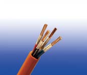
600/1000V Mica+XLPE Insulated, LSZH Sheathed Power Cables to IEC 60502-1 (2-5 Cores & Multicore)
FFX400 1mRZ1-R (CU/MGT+XLPE/LSZH 600/1000V Class 2)
APPLICATION
The cables are mainly used in power stations, mass transit underground passenger systems, airports, petrochemical plants, hotels, hospitals and high-rise buildings. This product type is CEand TUV approved.
STANDARDS
Basic design adapted from IEC 60502-1
FIRE PERFORMANCE
| Circuit Integrity | IEC 60331-21; EN 6387; BS 8491 |
| Flame Retardance (Single vertical wire or cable test) | IEC 60332-1-2; EN 60332-1-2 |
| Reduced fire Propagation (Vertically-mounted bundled wires & cables test) | IEC 60332-3-24; EN 60332-3-24 |
| Halogen Free | IEC 60754-1; EN 50267-2-1 |
| No Corrosive Gas emission | IEC 60754-2; EN 50267-2-2 |
| Minimum smoke emission | IEC 61034-2; EN 61034-2 |
VOLTAGE RATING
600/1000V
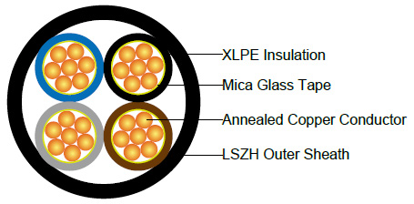
CABLE CONSTRUCTION
Conductor : The conductors shall be class 2 plain or metal-coated annealed copper in accordance with IEC 60228. Class 1 and class 5 conductor can be offered as option.
Fire Barrier : Mica glass tape.
Insulation : Thermosetting XLPE material and thickness shall be as per IEC 60502-1.
Outer Sheath : Thermoplastic halogen free compound ST8 as per IEC 60502-1.
Outer Sheath Option : UV resistance, hydrocarbon resistance, oil resistance, anti-rodent and anti-termite properties can be offered as option.
COLOUR CODE
Insulation Colour
2-core : Brown and blue.
3-core : Brown, black and grey.
4-core : Blue, brown, black and grey.
5-core : Green-and-yellow, blue, brown, black, grey.
Other colours can be offered upon request.
Sheath Colour : Black; other colours can be offered upon request.
PHYSICAL AND THERMAL PROPERTIES
Maximum temperature range during operation : 90°C
Maximum short circuit temperature (5 Seconds) : 250°C
Minimum bending radius
circular copper conductors OD≤25mm : 4 × Overall Diameter
circular copper conductors OD﹥25mm : 6 × Overall Diameter
shaped copper conductors : 8 × Overall Diameter
CONSTRUCTION PARAMETERS
| Conductor | FFX400 1mRZ1-R | |||||
|---|---|---|---|---|---|---|
| No. of Cores × Cross-sectional Area | Conductor Class | Nominal Insulation Thickness | Nominal Sheath Thickness | Approx. Overall Diameter | Approx. Weight | |
| no.×mm² | mm | mm | mm | kg/km | ||
| 2 cores | ||||||
| 2×1.5 | 2 | 0.7 | 1.8 | 11.6 | 139 | |
| 2×2.5 | 2 | 0.7 | 1.8 | 12.4 | 167 | |
| 2×4 | 2 | 0.7 | 1.8 | 13.5 | 211 | |
| 2×6 | 2 | 0.7 | 1.8 | 14.6 | 265 | |
| 2×10 | 2 | 0.7 | 1.8 | 16.5 | 370 | |
| 2×16 | 2 | 0.7 | 1.8 | 18.6 | 515 | |
| 2×25 | 2 | 0.9 | 1.8 | 22.0 | 756 | |
| 2×35 | 2 | 0.9 | 1.8 | 24.3 | 983 | |
| 2×50 | 2 | 1.0 | 1.8 | 27.4 | 1281 | |
| 2×70 | 2 | 1.1 | 1.8 | 31.4 | 1771 | |
| 2×95 | 2 | 1.1 | 1.9 | 35.4 | 2379 | |
| 2×120 | 2 | 1.2 | 2.0 | 39.2 | 2971 | |
| 2×150 | 2 | 1.4 | 2.2 | 43.5 | 3655 | |
| 2×185 | 2 | 1.6 | 2.3 | 48.3 | 4546 | |
| 2×240 | 2 | 1.7 | 2.5 | 54.3 | 5901 | |
| 2×300 | 2 | 1.8 | 2.6 | 59.8 | 7308 | |
| 2×400 | 2 | 2 | 2.9 | 67.1 | 9318 | |
| 3 cores | ||||||
| 3×1.5 | 2 | 0.7 | 1.8 | 12.2 | 168 | |
| 3×2.5 | 2 | 0.7 | 1.8 | 13.1 | 208 | |
| 3×4 | 2 | 0.7 | 1.8 | 14.3 | 269 | |
| 3×6 | 2 | 0.7 | 1.8 | 15.5 | 345 | |
| 3×10 | 2 | 0.7 | 1.8 | 17.5 | 495 | |
| 3×16 | 2 | 0.7 | 1.8 | 19.8 | 704 | |
| 3×25 | 2 | 0.9 | 1.8 | 23.5 | 1052 | |
| 3×35 | 2 | 0.9 | 1.8 | 26.0 | 1384 | |
| 3×50 | 2 | 1.0 | 1.8 | 29.3 | 1819 | |
| 3×70 | 2 | 1.1 | 1.9 | 33.8 | 2556 | |
| 3×95 | 2 | 1.1 | 2.0 | 38.3 | 3467 | |
| 3×120 | 2 | 1.2 | 2.1 | 42.4 | 4335 | |
| 3×150 | 2 | 1.4 | 2.3 | 46.8 | 5305 | |
| 3×185 | 2 | 1.6 | 2.4 | 52.1 | 6638 | |
| 3×240 | 2 | 1.7 | 2.6 | 58.5 | 8624 | |
| 3×300 | 2 | 1.8 | 2.7 | 64.4 | 10700 | |
| 3×400 | 2 | 2.0 | 3.0 | 72.1 | 13601 | |
| 3 cores + 1 core earth conductor | ||||||
| 3 cores | 1 core | |||||
| 3×16/10 | 2 | 0.7 | 0.7 | 1.8 | 20.4 | 818 |
| 3×25/16 | 2 | 0.9 | 0.7 | 1.8 | 24.3 | 1228 |
| 3×35/16 | 2 | 0.9 | 0.7 | 1.8 | 26.9 | 1560 |
| 3×50/25 | 2 | 1.0 | 0.9 | 1.8 | 30.3 | 2097 |
| 3×70/35 | 2 | 1.1 | 0.9 | 2.0 | 35.2 | 2935 |
| 3×95/50 | 2 | 1.1 | 1.0 | 2.1 | 39.7 | 3978 |
| 3×120/70 | 2 | 1.2 | 1.1 | 2.3 | 44.2 | 5067 |
| 3×150/70 | 2 | 1.4 | 1.1 | 2.4 | 48.8 | 6038 |
| 3×185/95 | 2 | 1.6 | 1.1 | 2.6 | 54.3 | 7643 |
| 3×240/120 | 2 | 1.7 | 1.2 | 2.8 | 61.1 | 9891 |
| 3×300/150 | 2 | 1.8 | 1.4 | 3.0 | 67.4 | 12260 |
| 3×400/185 | 2 | 2.0 | 1.6 | 3.2 | 75.4 | 15560 |
| 4 cores | ||||||
| 4×1.5 | 2 | 0.7 | 1.8 | 13.2 | 201 | |
| 4×2.5 | 2 | 0.7 | 1.8 | 14.2 | 253 | |
| 4×4 | 2 | 0.7 | 1.8 | 15.5 | 332 | |
| 4×6 | 2 | 0.7 | 1.8 | 16.9 | 431 | |
| 4×10 | 2 | 0.7 | 1.8 | 19.2 | 628 | |
| 4×16 | 2 | 0.7 | 1.8 | 21.7 | 901 | |
| 4×25 | 2 | 0.9 | 1.8 | 25.8 | 1358 | |
| 4×35 | 2 | 0.9 | 1.8 | 28.6 | 1796 | |
| 4×50 | 2 | 1.0 | 1.8 | 32.3 | 2369 | |
| 4×70 | 2 | 1.1 | 2.0 | 37.5 | 3358 | |
| 4×95 | 2 | 1.1 | 2.1 | 42.3 | 4537 | |
| 4×120 | 2 | 1.2 | 2.3 | 47.1 | 5703 | |
| 4×150 | 2 | 1.4 | 2.4 | 52.0 | 6984 | |
| 4×185 | 2 | 1.6 | 2.6 | 57.9 | 8740 | |
| 4×240 | 2 | 1.7 | 2.8 | 65.1 | 11362 | |
| 4×300 | 2 | 1.8 | 3.0 | 71.8 | 14145 | |
| 4×400 | 2 | 2.0 | 3.2 | 80.4 | 17984 | |
| Multicore | ||||||
| 5×1.5 | 2 | 0.7 | 1.8 | 14.3 | 260 | |
| 5×2.5 | 2 | 0.7 | 1.8 | 15.4 | 1544 | |
| 7×1.5 | 2 | 0.7 | 1.8 | 15.5 | 322 | |
| 7×2.5 | 2 | 0.7 | 1.8 | 16.7 | 2116 | |
| 10×1.5 | 2 | 0.7 | 1.8 | 19.4 | 438 | |
| 10×2.5 | 2 | 0.7 | 1.8 | 21.1 | 3000 | |
| 12×1.5 | 2 | 0.7 | 1.8 | 20.0 | 494 | |
| 12×2.5 | 2 | 0.7 | 1.8 | 21.8 | 3565 | |
| 14×1.5 | 2 | 0.7 | 1.8 | 21.0 | 554 | |
| 14×2.5 | 2 | 0.7 | 1.8 | 22.9 | 4135 | |
| 19×1.5 | 2 | 0.7 | 1.8 | 23.4 | 701 | |
| 19×2.5 | 2 | 0.7 | 1.8 | 25.5 | 5556 | |
| 21×1.5 | 2 | 0.7 | 1.8 | 24.5 | 763 | |
| 21×2.5 | 2 | 0.7 | 1.8 | 26.8 | 6128 | |
| 24×1.5 | 2 | 0.7 | 1.8 | 27.3 | 866 | |
| 24×2.5 | 2 | 0.7 | 1.8 | 29.8 | 6998 | |
| 30×1.5 | 2 | 0.7 | 1.8 | 28.9 | 1030 | |
| 30×2.5 | 2 | 0.7 | 1.8 | 31.6 | 8689 | |
| 40×1.5 | 2 | 0.7 | 1.8 | 32.4 | 9942 | |
| 40×2.5 | 2 | 0.7 | 1.9 | 35.7 | 11540 | |
| 48×1.5 | 2 | 0.7 | 1.8 | 35.8 | 11900 | |
| 48×2.5 | 2 | 0.7 | 1.9 | 39.4 | 13813 | |
| 61×1.5 | 2 | 0.7 | 1.9 | 39.4 | 15082 | |
| 61×2.5 | 2 | 0.7 | 2.0 | 43.3 | 17505 | |
ELECTRICAL PROPERTIES
Conductor operating temperature : 90°C
Ambient temperature : 30°C
Current-Carrying Capacities (Amp) according to BS 7671:2008 table 4E2A
| Conductor cross-sectional area | Ref. Method A (enclosed in conduit in thermally insulating wall etc.) | Ref. Method B (enclosed in conduit on a wall or in trunking etc.) | Ref. Method C (clipped direct) | Ref. Method E (in free air or on a perforated cable tray etc. horizontal or vertical) | ||||
|---|---|---|---|---|---|---|---|---|
| 1 two-core cable*, single-phase a.c. or d.c. | 1 three- or four-core cable*, three-phase a.c. | 1 two-core cable*, single-phase a.c. or d.c. | 1 three- or four-core cable*, three-phase a.c. | 1 two-core cable*, single-phase a.c. or d.c. | 1 three- or four-core cable*, three-phase a.c. | 1 two-core cable*, single-phase a.c. or d.c. | 1 three- or four-core cable*, three-phase a.c. | |
| 1 | 2 | 3 | 4 | 5 | 6 | 7 | 8 | 9 |
| mm² | A | A | A | A | A | A | A | A |
| 1.5 | 18.5 | 16.5 | 22 | 19.5 | 24 | 22 | 26 | 23 |
| 2.5 | 25 | 22 | 30 | 26 | 33 | 30 | 36 | 32 |
| 4 | 33 | 30 | 40 | 35 | 45 | 40 | 49 | 42 |
| 6 | 42 | 38 | 51 | 44 | 58 | 52 | 63 | 54 |
| 10 | 57 | 51 | 69 | 60 | 80 | 71 | 86 | 75 |
| 16 | 76 | 68 | 91 | 80 | 107 | 96 | 115 | 100 |
| 25 | 99 | 89 | 119 | 105 | 138 | 119 | 149 | 127 |
| 35 | 121 | 109 | 146 | 128 | 171 | 147 | 185 | 158 |
| 50 | 145 | 130 | 175 | 154 | 209 | 179 | 225 | 192 |
| 70 | 183 | 164 | 221 | 194 | 269 | 229 | 289 | 246 |
| 95 | 220 | 197 | 265 | 233 | 328 | 278 | 352 | 298 |
| 120 | 253 | 227 | 305 | 268 | 382 | 322 | 410 | 346 |
| 150 | 290 | 259 | 334 | 300 | 441 | 371 | 473 | 399 |
| 185 | 329 | 295 | 384 | 340 | 506 | 424 | 542 | 456 |
| 240 | 386 | 346 | 459 | 398 | 599 | 500 | 641 | 538 |
| 300 | 442 | 396 | 532 | 455 | 693 | 576 | 741 | 621 |
| 400 | - | - | 625 | 536 | 803 | 667 | 865 | 741 |
Note: *With or without a protective conductor.
Voltage Drop (Per Amp Per Meter) according to BS 7671:2008 table 4E2B
| Conductor cross-sectional area | Two-core cables, d.c. | Two-core cable, single-phase a.c. | Three- or four-core cable, three-phase a.c. | ||||
|---|---|---|---|---|---|---|---|
| 1 | 2 | 3 | 4 | ||||
| mm² | mV/A/m | mV/A/m | mV/A/m | ||||
| 1.5 | 31 | 31 | 27 | ||||
| 2.5 | 19 | 19 | 16 | ||||
| 4 | 12 | 12 | 10 | ||||
| 6 | 7.9 | 7.9 | 6.8 | ||||
| 10 | 4.7 | 4.7 | 4.0 | ||||
| 16 | 2.9 | 2.9 | 2.5 | ||||
| r | x | z | r | x | z | ||
| 25 | 1.85 | 1.85 | 0.160 | 1.90 | 1.60 | 0.140 | 1.65 |
| 35 | 1.35 | 1.35 | 0.155 | 1.35 | 1.15 | 0.135 | 1.15 |
| 50 | 0.98 | 0.99 | 0.155 | 1.00 | 0.86 | 0.135 | 0.87 |
| 70 | 0.67 | 0.67 | 0.150 | 0.69 | 0.59 | 0.130 | 0.60 |
| 95 | 0.49 | 0.50 | 0.150 | 0.52 | 0.43 | 0.130 | 0.45 |
| 120 | 0.39 | 0.40 | 0.145 | 0.42 | 0.34 | 0.130 | 0.37 |
| 150 | 0.31 | 0.32 | 0.145 | 0.35 | 0.38 | 0.125 | 0.30 |
| 185 | 0.25 | 0.26 | 0.145 | 0.29 | 0.22 | 0.125 | 0.26 |
| 240 | 0.195 | 0.200 | 0.140 | 0.24 | 0.175 | 0.125 | 0.21 |
| 300 | 0.155 | 0.160 | 0.140 | 0.21 | 0.140 | 0.120 | 0.185 |
| 400 | 0.120 | 0.130 | 0.140 | 0.190 | 0.115 | 0.120 | 0.165 |
r = conductor resistance at operating temperature
x = reactance
z = impedance