450/750V & 600/1000V Mica+LSZH Insulated Power Cables (Single Core)
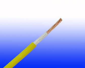
FFX100 07mZ1-R (CU/MGT+LSZH 450/750V Class 2)
FFX100 1mZ1-R (CU/MGT+LSZH 600/1000V Class 2)
APPLICATION
This cable is used in fire extinguishing systems, sprinklers, control panels, and exit lights in high-rise buildings, hotels, hospitals,sub-ways,and public acilities.
STANDARDS
FIRE PERFORMANCE
| Circuit Integrity |
IEC 60331-21; BS 6387 CWZ; DIN VDE 0472-814(FE180); CEI 20-36/2-1; SS229-1; NBN C 30-004 (cat. F3); NF C32-070-2.3(CR1) |
| System circuit integrity |
DIN 4102-12, E30 depending on lay system |
| Flame Retardance (Single Vertical Wire Test) |
EN 60332-1-2; IEC 60332-1-2; BS EN 60332-1-2; VDE 0482-332-1; NBN C 30-004 (cat. F1); NF C32-070-2.1(C2); CEI 20-35/1-2; EN 50265-2-1*;DIN VDE 0482-265-2-1* |
| Reduced Fire Propagation (Vertically-mounted bundled wires &cable test) |
EN 60332-3-24 (cat. C); IEC 60332-3-24; BS EN 60332-3-24; VDE 0482-332-3; NBN C 30-004 (cat. F2); NF C32-070-2.2(C1); CEI 20-22/3-4; EN 50266-2-4*; DIN VDE 0482-266-2-4 |
| Halogen Free |
IEC 60754-1; EN 50267-2-1; DIN VDE 0482-267-2-1; CEI 20-37/2-1; BS 6425-1* |
| No Corrosive Gas Emission |
IEC 60754-2; EN 50267-2-2; DIN VDE 0482-267-2-2; CEI 20-37/2-2; BS 6425-2* |
| Minimum Smoke Emission |
IEC 61034-1&2; EN 61034 -1&2; DIN VDE 0482-1034-1&2; CEI 20-37/3-1&2; EN 50268-1&2*; BS 7622-1&2* |
| No Toxic gases |
NES 02-713; NF C 20-454 |
Note: Asterisk * denotes superseded standard.
VOLTAGE RATING
450/750V & 600/1000V
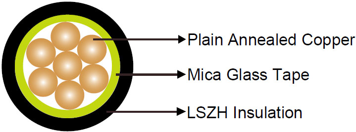
CABLE CONSTRUCTION
| Conductor |
Plain annealed copper wire, stranded according to IEC(EN) 60228 class 2 |
| Fire Barrier |
Mica glass tape |
| Insulation |
Thermoplastic LSZH compound type LTS3 as per BS 7655-6.1 (Thermosetting LSZH compound type SW2-SW4 as per BS 7655-2.6 can be offered.). UV resistance, hydrocarbon resistance, oil resistance, anti rodent and anti termite properties can be offered as option |
COLOUR CODE
Insulation Colour: Black (other colors upon request)
PHYSICAL AND THERMAL PROPERTIES
| Temperature range during operation (fixed state) |
-30°C – +90°C |
| Temperature range during installation (mobile state) |
-20°C – +50°C |
| Minimum bending radius |
6 x Overall Diameter |
ELECTRICAL PROPERTIES
| Dielectric test |
600/1000V: 3500 V r.m.s. x 5’(core/core); 450/750V: 2500 V r.m.s. x 5’(core/core) |
| Insulation resistance |
20 MΩ x km (at 20°C) |
| Short circuit temperature |
250°C |
CONSTRUCTION PARAMETERS
| Conductor |
FFX100 07mZ1-R |
FFX100 1mZ1-R |
| Nominal Cross Section Area |
No./Nominal Diameter of Strands |
Nominal Insulation Thickness |
Nominal Overall Diameter |
Approx. Weight |
Nominal Insulation Thickness |
Nominal Overall Diameter |
Approx. Weight |
| mm2 |
No./mm |
mm |
mm |
kg/km |
mm |
mm |
kg/km |
| 1.5 |
7/0.53 |
0.7 |
3.5 |
25 |
0.8 |
3.8 |
30 |
| 2.5 |
7/0.67 |
0.8 |
4.1 |
35 |
0.8 |
4.2 |
40 |
| 4 |
7/0.85 |
0.8 |
4.6 |
52 |
1 |
5.3 |
70 |
| 6 |
7/1.04 |
0.8 |
5.2 |
72 |
1 |
6 |
96 |
| 10 |
7/1.35 |
1 |
6.5 |
120 |
1 |
6.6 |
130 |
| 16 |
7/1.70 |
1 |
7.6 |
180 |
1 |
7.7 |
200 |
| 25 |
7/2.14 |
1.2 |
9 |
275 |
1.2 |
9.1 |
290 |
| 35 |
7/2.52 |
1.2 |
10.2 |
370 |
1.2 |
10.3 |
390 |
| 50 |
19/2.52 |
1.4 |
11.8 |
500 |
1.4 |
11.9 |
520 |
| 70 |
19/2.14 |
1.4 |
13.4 |
700 |
1.4 |
13.5 |
730 |
| 95 |
19.2.52 |
1.6 |
15.8 |
980 |
1.6 |
15.9 |
990 |
| 150 |
37/2.52 |
1.8 |
18.8 |
1500 |
1.8 |
18.9 |
1520 |
| 185 |
37/2.52 |
2 |
21 |
1900 |
2 |
21.2 |
1900 |
| 240 |
37/2.52 |
2.2 |
25.7 |
2500 |
2.2 |
25.8 |
2550 |
| 300 |
37/2.52 |
2.4 |
28.6 |
3140 |
2.4 |
28.8 |
3150 |
| 400 |
61/2.85 |
2.6 |
32 |
4000 |
2.6 |
32.2 |
4000 |
| 500 |
61/3.20 |
2.8 |
35.5 |
5000 |
2.8 |
35.7 |
5000 |
| 630 |
127/2.52 |
2.8 |
39.5 |
6300 |
2.8 |
39.7 |
6360 |
ELECTRICAL PROPERTIES
| Conductor Operating Temperature |
90°C |
| Ambient Temperature |
30°C |
Current-Carrying Capacities (Amp)
| Conductor cross-sectional area |
Reference Method A (enclosed in conduit in thermally insulating wall etc) |
Reference Method B (enclosed in conduit on a wall or intrunking etc) |
Reference Method C (clipped direct) |
Reference Method F (in free air or on a perforated cable tray, horizontal orvertical etc) Touching |
Reference Method G (in free air) Spaced by one cable diameter |
| 2 cables, single-phase a.c. or d.c. |
3 or 4 cables, three-phase a.c. |
2 cables, single-phase a.c. or d.c |
3 or 4 cables, three-phase a.c. |
2 cables, single-phase a.c. or d.c. flat and touching |
3 or 4 cables, three-phase a.c. flat and touching or trefoil |
2 cables,single-phase a.c. or d.c. flat |
3 cables, three-phase a.c. flat |
3 cables, three-phase a.c. trefoil |
2 cables, single-phase a.c. or d.c. or 3 cables three-phase a.c. flat |
| Horizontal |
Vertical |
| 1 |
2 |
3 |
4 |
5 |
6 |
7 |
8 |
9 |
10 |
11 |
12 |
| mm2 |
A |
A |
A |
A |
A |
A |
A |
A |
A |
A |
A |
| 1.5 |
19 |
17 |
23 |
20 |
25 |
23 |
- |
- |
- |
- |
- |
| 2.5 |
26 |
23 |
31 |
28 |
34 |
31 |
- |
- |
- |
- |
- |
| 4 |
35 |
31 |
42 |
37 |
46 |
41 |
- |
- |
- |
- |
- |
| 6 |
45 |
40 |
54 |
48 |
59 |
54 |
- |
- |
- |
- |
- |
| 10 |
61 |
54 |
75 |
66 |
81 |
74 |
- |
- |
- |
- |
- |
| 16 |
81 |
73 |
100 |
88 |
109 |
99 |
- |
- |
- |
- |
- |
| 25 |
106 |
95 |
133 |
117 |
143 |
130 |
161 |
141 |
135 |
182 |
161 |
| 35 |
131 |
117 |
164 |
144 |
176 |
161 |
200 |
176 |
169 |
226 |
201 |
| 50 |
158 |
141 |
198 |
175 |
228 |
209 |
242 |
216 |
207 |
275 |
246 |
| 70 |
200 |
179 |
253 |
222 |
293 |
268 |
310 |
279 |
268 |
353 |
318 |
| 95 |
241 |
216 |
306 |
269 |
355 |
326 |
377 |
342 |
328 |
430 |
389 |
| 120 |
278 |
249 |
354 |
312 |
413 |
379 |
437 |
400 |
383 |
500 |
454 |
| 150 |
318 |
285 |
393 |
342 |
476 |
436 |
504 |
464 |
444 |
577 |
527 |
| 185 |
362 |
324 |
449 |
384 |
545 |
500 |
575 |
533 |
510 |
661 |
605 |
| 240 |
424 |
380 |
528 |
450 |
644 |
590 |
679 |
634 |
607 |
781 |
719 |
| 300 |
486 |
435 |
306 |
514 |
743 |
681 |
783 |
736 |
703 |
902 |
833 |
| 400 |
- |
- |
383 |
584 |
868 |
793 |
940 |
868 |
823 |
1085 |
1008 |
| 500 |
- |
- |
783 |
666 |
990 |
904 |
1083 |
998 |
946 |
1253 |
1169 |
| 630 |
- |
- |
900 |
764 |
113 |
1033 |
1254 |
1151 |
1088 |
1454 |
1362 |
Voltage Drop (Per Amp Per Meter)
| Nominal
Cross Section
Area |
2 cablesd.c. |
2 cables, single-phase a.c. |
3 or 4 cables, three-phase a.c. |
| Ref. Methods A and B (enclosed in conduit or trunking) |
Ref. Methods C, F&G(clipped direct, on trays or in free air) |
Ref. Methods 3 and 4 (enclosed in conduit etc, inor on a wall) |
Ref. Methods C, F&G (clipped direct, on trays or in free air) |
| Cables touching,Trefoil |
Cables touching,Flat |
Cables spaced*, Flat |
| 1 |
2 |
3 |
touching 4 |
spaced*5 |
6 |
7 |
8 |
9 |
| mm2 |
mV/A/m |
mV/A/m |
mV/A/m |
mV/A/m |
mV/A/m |
mV/A/m |
mV/A/m |
mV/A/m |
| 1.5 |
31 |
31 |
31 |
31 |
27 |
27 |
27 |
27 |
| 2.5 |
19 |
19 |
19 |
19 |
16 |
16 |
16 |
16 |
| 4 |
12 |
12 |
12 |
12 |
10 |
10 |
10 |
10 |
| 6 |
7.9 |
7.9 |
7.9 |
7.9 |
6.8 |
6.8 |
6.8 |
6.8 |
| 10 |
4.7 |
4.7 |
4.7 |
4.7 |
4.0 |
4.0 |
4.0 |
4.0 |
| 16 |
2.9 |
2.9 |
2.9 |
2.9 |
2.5 |
2.5 |
2.5 |
2.5 |
| |
|
r |
x |
z |
r |
x |
z |
r |
x |
z |
r |
x |
z |
r |
x |
z |
r |
x |
z |
r |
x |
z |
| 25 |
1.85 |
1.85 |
0.31 |
1.90 |
1.85 |
0.190 |
1.85 |
1.85 |
0.28 |
1.85 |
1.60 |
0.27 |
1.65 |
1.60 |
0.165 |
1.60 |
1.60 |
0.190 |
1.60 |
1.60 |
0.27 |
1.65 |
| 35 |
1.35 |
1.35 |
0.29 |
1.35 |
1.35 |
0.180 |
1.35 |
1.35 |
0.27 |
1.35 |
1.15 |
0.25 |
1.15 |
1.15 |
0.155 |
1.15 |
1.15 |
0.180 |
1.15 |
1.15 |
0.26 |
1.20 |
| 50 |
0.99 |
1.00 |
0.29 |
1.05 |
0.99 |
0.180 |
1.00 |
0.99 |
0.27 |
1.00 |
0.87 |
0.25 |
0.90 |
0.86 |
0.155 |
0.87 |
0.86 |
0.180 |
0.87 |
0.86 |
0.26 |
0.89 |
| 70 |
0.68 |
0.70 |
0.28 |
0.75 |
0.68 |
0.175 |
0.71 |
0.68 |
0.26 |
0.73 |
0.60 |
0.24 |
0.65 |
0.59 |
0.150 |
0.61 |
0.59 |
0.175 |
0.62 |
0.59 |
0.25 |
0.65 |
| 95 |
0.49 |
0.51 |
0.27 |
0.58 |
0.49 |
0.170 |
0.52 |
0.49 |
0.26 |
0.56 |
0.44 |
0.23 |
0.50 |
0.43 |
0.145 |
0.50 |
0.43 |
0.170 |
0.45 |
0.43 |
0.25 |
0.49 |
| 120 |
0.39 |
0.41 |
0.26 |
0.48 |
0.39 |
0.165 |
0.43 |
0.39 |
0.25 |
0.47 |
0.35 |
0.23 |
0.42 |
0.34 |
0.140 |
0.37 |
0.34 |
0.165 |
0.38 |
0.34 |
0.24 |
0.42 |
| 150 |
032 |
0.33 |
0.26 |
0.43 |
0.32 |
0.165 |
0.36 |
0.32 |
0.25 |
0.41 |
0.29 |
0.23 |
0.37 |
0.28 |
0.140 |
0.31 |
0.28 |
0.165 |
0.32 |
0.28 |
0.24 |
0.37 |
| 185 |
0.25 |
0.27 |
0.26 |
0.37 |
0.26 |
0.165 |
0.30 |
0.25 |
0.25 |
0.36 |
0.23 |
0.23 |
0.32 |
0.22 |
0.140 |
0.26 |
0.22 |
0.165 |
0.28 |
0.22 |
0.24 |
0.33 |
| 240 |
0.190 |
0.21 |
0.26 |
0.33 |
0.20 |
0.160 |
0.25 |
0.195 |
0.25 |
0.31 |
0.185 |
0.22 |
0.29 |
0.170 |
0.140 |
0.22 |
0.170 |
0.165 |
0.24 |
0.170 |
0.24 |
0.29 |
| 300 |
0.155 |
0.175 |
0.25 |
0.31 |
0.160 |
0.160 |
0.22 |
0.155 |
0.25 |
0.29 |
0.150 |
0.22 |
0.27 |
0.140 |
0.140 |
0.195 |
0.135 |
0.160 |
0.21 |
0.135 |
0.24 |
0.27 |
| 400 |
0.120 |
0.140 |
0.25 |
0.29 |
0.130 |
0.155 |
0.20 |
0.125 |
0.24 |
0.27 |
0.125 |
0.22 |
0.25 |
0.110 |
0.135 |
0.175 |
0.110 |
0.160 |
0.195 |
0.110 |
0.24 |
0.26 |
| 500 |
0.093 |
0.120 |
0.25 |
0.28 |
0.105 |
0.155 |
0.185 |
0.098 |
0.24 |
0.26 |
0.100 |
0.22 |
0.24 |
0.090 |
0.135 |
0.160 |
0.088 |
0.160 |
0.180 |
0.085 |
0.24 |
0.25 |
| 630 |
0.072 |
0.100 |
0.25 |
0.27 |
0.086 |
0.155 |
0.175 |
0.078 |
0.24 |
0.25 |
0.088 |
0.21 |
0.23 |
0.074 |
0.135 |
0.150 |
0.071 |
0.160 |
0.170 |
0.068 |
0.23 |
0.24 |
Note: *Spacings larger than one cable diameter will result in a large voltage drop.
r = conductor resistance at operating temperature
x = reactance
z = impedance