600/1000V XLPE Insulated, LSZH Sheathed, Double Steel Tape Armoured Power Cables (2 Cores)
FTX400 1RZ1F2Z1-R (CU/XLPE/LSZH/DSTA/LSZH 600/1000V Class 2)
APPLICATION
The cables are mainly used in power stations, mass transit underground passenger systems, airports, petrochemical plants, hotels, hospitals, and high-rise buildings.
 |
 |
STANDARDS
- Basic design adapted to IEC 60502-1
FIRE PERFORMANCE
| Flame Retardance (Single Vertical Wire Test) | EN 60332-1-2; IEC 60332-1-2; BS EN 60332-1-2; VDE 0482-332-1; NBN C 30-004 (cat. F1); NF C32-070-2.1(C2); CEI 20-35/1-2; EN 50265-2-1*; DIN VDE 0482-265-2-1* |
| Reduced Fire Propagation (Vertically-mounted bundled wires & cable test) | EN 60332-3-24 (cat. C); IEC 60332-3-24; BS EN 60332-3-24; VDE 0482-332-3; NBN C 30-004 (cat. F2); NF C32-070-2.2(C1);CEI 20-22/3-4; EN 50266-2-4*; DIN VDE 0482-266-2-4 |
| Halogen Free | IEC 60754-1; EN 50267-2-1; DIN VDE 0482-267-2-1; CEI 20-37/2-1; BS 6425-1* |
| No Corrosive Gas Emission | IEC 60754-2; EN 50267-2-2; DIN VDE 0482-267-2-2; CEI 20-37/2-2 ; BS 6425-2* |
| Minimum Smoke Emission | IEC 61034-1&2; EN 61034 -1&2; DIN VDE 0482-1034-1&2; CEI 20-37/3-1&2; EN 50268-1&2*; BS 7622-1&2* |
| No Toxic gases | NES 02-713; NF C 20-454 |
Note: Asterisk * denotes superseded standard.
VOLTAGE RATING
600/1000 V
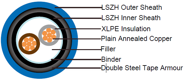
CABLE CONSTRUCTION
| Conductor | Plain annealed copper wire, normal stranded or compact stranded according to IEC 60228 class 2 |
| Insulation | Extruded XLPE compound |
| Filler, binder and inner covering | PP, PET, LSZH |
| Armouring | Double steel tape armouring |
| Outer Sheath | Thermoplastic LSZH compound type LTS3 as per BS 7655-6.1. UV resistance, hydrocarbon resistance, oil resistance, anti rodent and anti termite properties can be offered as option |
COLOUR CODE
Insulation Colour as per BS7671
| With Earth Conductor | Without Earth Conductor | |
| 2 Cores | - | Brown, Blue |
Sheath Colour: Black (other colors upon request)
PHYSICAL AND THERMAL PROPERTIES
| Maximum temperature range during operation (XLPE) | 90°C |
| Maximum short circuit temperature (5 Seconds) | 250°C |
| Minimum bending radius | 10 x Overall Diameter |
CONSTRUCTION PARAMETERS
| Conductor | FTX400 1RZ1F2Z1-R | |||||||
|---|---|---|---|---|---|---|---|---|
| No. of Core X Cross Section | No./Nominal Diameter of Strands | Diameter Overall Conducrtor | Nominal Insulation Thickness | Steel Tape Thickness | Nominal Sheath Thickness | Nominal Overall Diatemer | Max.DC resistance of conductor @20°C | Approx.Weight |
| mm2 | No/mm | mm | mm | mm | mm | mm | Ω/km | Kg/km |
| 2x6 | 7/1.04 | 2.90 | 0.7 | 0.2 | 1.8 | 16.8 | 3.08 | 417 |
| 2x10 | 7/1.35 | 3.75 | 0.7 | 0.2 | 1.8 | 18.5 | 1.83 | 539 |
| 2x16 | 7/1.70 | 4.75 | 0.7 | 0.2 | 1.8 | 20.5 | 1.15 | 704 |
| 2x25 | 7/2.14 | 5.85 | 0.9 | 0.2 | 1.8 | 23.5 | 0.727 | 971 |
| 2x35 | 7/2.52 | 6.90 | 0.9 | 0.2 | 1.8 | 25.6 | 0.524 | 1,216 |
| 2x50 | 19/1.78 | 8.15 | 1.0 | 0.2 | 1.8 | 28.5 | 0.387 | 1,582 |
| 2x70 | 19/2.14 | 9.75 | 1.1 | 0.2 | 1.9 | 32.3 | 0.268 | 2081 |
| 2x95 | 19/2.52 | 11.45 | 1.1 | 0.2 | 2.0 | 36.4 | 0.193 | 2749 |
| 2x120 | 37/2.03 | 12.85 | 1.2 | 0.5 | 2.2 | 41.1 | 0.153 | 3,727 |
| 2x150 | 37/2.25 | 14.30 | 1.4 | 0.5 | 2.3 | 45.1 | 0.124 | 4,509 |
| 2x185 | 37/2.52 | 15.95 | 1.6 | 0.5 | 2.5 | 49.9 | 0.0991 | 5,523 |
| 2x240 | 61/2.25 | 18.25 | 1.7 | 0.5 | 2.6 | 55.3 | 0.0754 | 6981 |
| 2x300 | 61/2.52 | 20.40 | 1.8 | 0.5 | 2.8 | 60.7 | 0.0601 | 8,383 |
| 2x400 | 61/2.85 | 23.35 | 2.0 | 0.5 | 3.0 | 67.9 | 0.0470 | 10,897 |
ELECTRICAL PROPERTIES
| Conductor Operating Temperature | 90°C |
| Ambient Temperature | 30°C |
Current-Carrying Capacities (Amp)
Conductor cross-sectional area |
Reference Method C (clipped direct) |
Reference Method E (in free air or on a perforated cable tray, horizontal or vertical) |
Reference Method D (direct in in groud or in ducting in groud.in or around buildings) |
|||
|---|---|---|---|---|---|---|
1 two-core cable*, single-phase a.c. or d.c. |
1 three-or four core cable*,three-phase a.c. |
1 two-core cable*, single-phase a.c. or d.c. |
1 three-or four core cable*,three-phase a.c. |
1 two-core cable*, single-phase a.c. or d.c. |
1 three-or fourcore cable*,three-phase a.c. |
|
1 |
2 |
3 |
4 |
5 |
6 |
7 |
mm2 |
A |
A |
A |
A |
A |
A |
1.5 |
27 |
23 |
29 |
25 |
25 |
21 |
2.5 |
36 |
31 |
39 |
33 |
33 |
28 |
4 |
49 |
42 |
52 |
44 |
43 |
36 |
6 |
62 |
53 |
66 |
56 |
53 |
44 |
10 |
85 |
73 |
90 |
78 |
71 |
58 |
16 |
110 |
94 |
115 |
99 |
91 |
75 |
25 |
146 |
124 |
152 |
131 |
116 |
96 |
35 |
180 |
154 |
188 |
162 |
139 |
115 |
50 |
219 |
187 |
228 |
197 |
164 |
135 |
70 |
279 |
238 |
291 |
251 |
203 |
167 |
95 |
338 |
289 |
354 |
304 |
239 |
197 |
120 |
392 |
335 |
410 |
353 |
271 |
223 |
150 |
451 |
386 |
472 |
406 |
306 |
251 |
185 |
515 |
441 |
539 |
463 |
343 |
281 |
240 |
607 |
520 |
636 |
546 |
395 |
324 |
300 |
698 |
599 |
732 |
628 |
446 |
365 |
Voltage Drop (Per Amp Per Meter)
| Conductor cross-sectional area | Two-core cables, d.c. | Two-core cable, single-phase a.c. | Three-or four core cable, three-phase a.c. | ||||
|---|---|---|---|---|---|---|---|
| 1 | 2 | 3 | 4 | ||||
| mm2 | mV/A/m | mV/A/m | mV/A/m | ||||
| 1.5 | 31 | 31 | 27 | ||||
| 2.5 | 19 | 19 | 16 | ||||
| 4 | 12 | 12 | 10 | ||||
| 6 | 7.9 | 7.9 | 6.8 | ||||
| 10 | 4.7 | 4.7 | 4.0 | ||||
| 16 | 2.9 | 2.9 | 2.5 | ||||
| r | x | z | r | x | z | ||
| 25 | 1.85 | 1.85 | 0.160 | 1.90 | 1.60 | 0.140 | 1.65 |
| 35 | 1.35 | 1.35 | 0.155 | 1.35 | 1.15 | 0.135 | 1.15 |
| 50 | 0.98 | 0.99 | 0.155 | 1.00 | 0.86 | 0.135 | 0.87 |
| 70 | 0.67 | 0.67 | 0.150 | 0.69 | 0.59 | 0.130 | 0.60 |
| 95 | 0.49 | 0.50 | 0.150 | 0.52 | 0.43 | 0.130 | 0.45 |
| 120 | 0.39 | 0.40 | 0.145 | 0.42 | 0.34 | 0.130 | 0.37 |
| 150 | 0.31 | 0.32 | 0.145 | 0.35 | 0.38 | 0.125 | 0.30 |
| 185 | 0.25 | 0.26 | 0.145 | 0.29 | 0.22 | 0.125 | 0.26 |
| 240 | 0.195 | 0.200 | 0.140 | 0.24 | 0.175 | 0.125 | 0.21 |
| 300 | 0.155 | 0.160 | 0.140 | 0.21 | 0.140 | 0.120 | 0.185 |
Note: *Spacings larger than one cable diameter will result in a large voltage drop.
r = conductor resistance at operating temperature
x = reactance
z = impedance