FIREROL Medium Wall Multicore Unscreened Cables 300/500 V or 0.6/1 kV
EN 50264-3-2 (FRL-MW-05M / FRL-MW-1M)
Application
-Used as power and control cable for protected installations inside and outside of rail and transport vehicles, where handling and installation cost are an important factor.
-Used in control,auxillary and main circuit wiring such as cable harnesses, switchboards and control panels, driver desks etc.
Construction
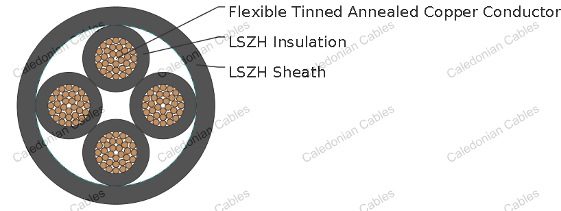
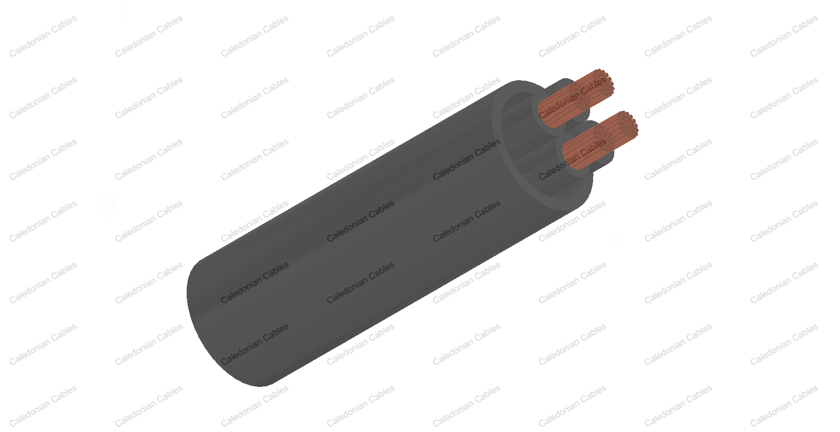
| Conductor | Flexible tinned annealed copper wires, stranded as per HD 383 (IEC 60228) class 5 |
| Insulation | LSZH elastomeric compound as defined in EN 50264-1 (EM 101 to EI 104) |
| Outer Sheath | LSZH elastomeric compound as defined in EN 50264-1 (EM 101 to EI 104) |
Electrical & Mechanical Properties
| Nominal Voltage | 300/500 V or 0.6/1 kV |
| Maximum Conductor Temperature | 90°C ( fixed installation ) |
| Minimum Permissible Ambient Temperature | -25°C/-40°C ( fixed installation ) |
| Bending Radius |
Fixed installation : 4 x Overall Diameter (D<12mm); 5 x Overall Diameter (D>12mm) Flexible installation : 8 x Overall Diameter (D<12mm); 10 x Overall Diameter (D>12mm) |
Chemical & Environmental Propertie
| EN 60684-2 | No fluorine |
| EN 50305; EN 60811-2-1 | Resistance to mineral oil & fuel oil, acid & alkali |
| EN 50305 | Resistance to ozone |
Fire Performance for rolling stock application
| EN 50306-2 | Hazard levels HL1, HL2, HL3 |
| DIN 5510-2 | Protection level 1/2/3/4 |
| BS 6853 | Interior use 1a, 1b, II; Exterior use 1a, 1b, II |
| NF F 16-101 | F0 |
| EN 54454-2 | R15 Interior/ R16 Exterior HL1, HL2, HL3 |
Fire Performance in General
| EN 50265-2-1; IEC 60332-1-2; NF C 32-070 2.1 (C2) | Vertical flame propogation for a single insulated wire or cable |
| EN 50266-2-4 + EN 50305; IEC 60332-3-24; NF C 32-070 2.2 (C1); VDE 0472 Teil 804 | Vertical flame spread of vertically mounted bunched wires or cables |
| EN 50268-2; IEC 61034-2; NF C 32-073; NF C 20-902; NF F 16 101; VDE 0472 Teil 816 | Low Smoke Emission |
| EN 50267-2-1; IEC 60754-1; NF C 32-074; NF C 20-454; VDE 0472 Teil 815 | Halogen Free |
|
EN 50267-2-2/3; IEC 60754-2; NF C 32-074;NF C 20-453; VDE 0472 Teil 813 |
Low Corrosivity (Acidity & Conductivity) |
| EN 50305; NF X 70-100; NF F 63 808; TM1-04; BS6853 | Low Toxicity |
| NF F 63 808; BS6853; NF F 16 101 | Smoke index |
| EN50200: 2000 | Resistance to fire of unprotected small cable for use in emergency circuits 4 classifications are defined: PH 15,30,60, or 90mins; |
| IEC60331-21 | The circuit integrity test under fire of cables rated 0.6/1.0kV and below |
| EN45545-2 | Requirement for fire behavior of materials & components R15/R16 |
FRL-MW-05M 300/500 V
| Nominal Cross-Sectional Area (a) | Conductor Diameter (b) | Min. Mean Thickness of Insulation | Core Dimensions | Min. Average Sheath Thickness | Overall Diameter | Weight | Max. Conductor Resistance | Min. Insulation Resistance | |||
|---|---|---|---|---|---|---|---|---|---|---|---|
| EI 110 | EI 106/7/8/9 | ||||||||||
| Min. Acc.to EN | Max. Acc.to EN | Min. | Max. | 20°C | 20°C | 20°C | |||||
| n x mm² | mm | mm | mm | mm | mm | mm | mm | kg/km | Ω/km | MΩ x km | MΩ x km |
| 2 x 1 | 1.25 | 0.4 | 2.0 | 2.4 | 0.6 | 5.3 | 6.2 | 40 | 20.0 | 15.0 | 7.5 |
| 4 x 1 | 1.25 | 0.4 | 2.0 | 2.4 | 0.6 | 6.1 | 7.2 | 70 | 20.0 | 15.0 | 7.5 |
| 7 x 1 | 1.25 | 0.4 | 2.0 | 2.4 | 0.7 | 7.5 | 8.7 | 120 | 20.0 | 15.0 | 7.5 |
| 9 x 1 | 1.25 | 0.4 | 2.0 | 2.4 | 0.7 | 9.1 | 10.6 | 160 | 20.0 | 15.0 | 7.5 |
| 12 x 1 | 1.25 | 0.4 | 2.0 | 2.4 | 0.7 | 9.8 | 11.5 | 190 | 20.0 | 15.0 | 7.5 |
| 19 x 1 | 1.25 | 0.4 | 2.0 | 2.4 | 0.8 | 11.7 | 13.7 | 290 | 20.0 | 15.0 | 7.5 |
| 24 x 1 | 1.25 | 0.4 | 2.0 | 2.4 | 1.0 | 14.1 | 16.5 | 390 | 20.0 | 15.0 | 7.5 |
| 32 x 1 | 1.25 | 0.4 | 2.0 | 2.4 | 1.0 | 15.5 | 18.2 | 490 | 20.0 | 15.0 | 7.5 |
| 37 x 1 | 1.25 | 0.4 | 2.0 | 2.4 | 1.0 | 16.1 | 18.9 | 550 | 20.0 | 15.0 | 7.5 |
| 40 x 1 | 1.25 | 0.4 | 2.0 | 2.4 | 1.0 | 16.7 | 19.6 | 600 | 20.0 | 15.0 | 7.5 |
| 4 x 1.5 | 1.5 | 0.5 | 2.4 | 2.9 | 0.7 | 7.3 | 8.6 | 110 | 13.7 | 14.0 | 7.0 |
| 7 x 1.5 | 1.5 | 0.5 | 2.4 | 2.9 | 0.7 | 8.7 | 10.2 | 170 | 13.7 | 14.0 | 7.0 |
| 9 x 1.5 | 1.5 | 0.5 | 2.4 | 2.9 | 0.8 | 10.9 | 12.7 | 230 | 13.7 | 14.0 | 7.0 |
| 12 x 1.5 | 1.5 | 0.5 | 2.4 | 2.9 | 0.8 | 11.8 | 13.8 | 280 | 13.7 | 14.0 | 7.0 |
| 19 x 1.5 | 1.5 | 0.5 | 2.4 | 2.9 | 1.0 | 14.2 | 16.6 | 440 | 13.7 | 14.0 | 7.0 |
| 24 x 1.5 | 1.5 | 0.5 | 2.4 | 2.9 | 1.0 | 16.6 | 19.5 | 560 | 13.7 | 14.0 | 7.0 |
| 32 x 1.5 | 1.5 | 0.5 | 2.4 | 2.9 | 1.2 | 18.7 | 21.9 | 720 | 13.7 | 14.0 | 7.0 |
| 37 x 1.5 | 1.5 | 0.5 | 2.4 | 2.9 | 1.2 | 19.5 | 22.8 | 820 | 13.7 | 14.0 | 7.0 |
| 4 x 2.5 | 1.95 | 0.5 | 2.9 | 3.4 | 0.7 | 8.3 | 9.8 | 150 | 8.21 | 13.0 | 6.5 |
| 7 x 2.5 | 1.95 | 0.5 | 2.9 | 3.4 | 0.8 | 10.2 | 11.9 | 240 | 8.21 | 13.0 | 6.5 |
| 9 x 2.5 | 1.95 | 0.5 | 2.9 | 3.4 | 1.0 | 12.9 | 15.1 | 350 | 8.21 | 13.0 | 6.5 |
| 12 x 2.5 | 1.95 | 0.5 | 2.9 | 3.4 | 1.0 | 13.9 | 16.3 | 420 | 8.21 | 13.0 | 6.5 |
| 19 x 2.5 | 1.95 | 0.5 | 2.9 | 3.4 | 1.0 | 16.3 | 19.1 | 640 | 8.21 | 13.0 | 6.5 |
| 24 x 2.5 | 1.95 | 0.5 | 2.9 | 3.4 | 1.2 | 19.6 | 22.9 | 840 | 8.21 | 13.0 | 6.5 |
(a)= One earth conductor (green/yellow) can be included upon request
(b)= For information, indicative only
FRL-MW-1M 0.6/1 kV
| Nominal Cross-Sectional Area (a) | Conductor Diameter (b) | Min. Mean Thickness of Insulation | Core Dimensions | Min. Average Sheath Thickness | Overall Diameter | Weight | Max. Conductor Resistance | Min. Insulation Resistance | |||
|---|---|---|---|---|---|---|---|---|---|---|---|
| EI 110 | EI 106/7/8/9 | ||||||||||
| Min. Acc.to EN | Max. Acc.to EN | Min. | Max. | 20°C | 20°C | 20°C | |||||
| n x mm² | mm | mm | mm | mm | mm | mm | mm | kg/km | Ω/km | MΩ x km | MΩ x km |
| TWO CORES | |||||||||||
| 1.5 | 1.5 | 0.7 | 2.8 | 3.3 | 0.70 | 7.2 | 9.0 | 70 | 13.7 | 21.0 | 10.5 |
| 2.5 | 1.95 | 0.7 | 3.2 | 3.8 | 0.70 | 8.0 | 10.0 | 100 | 8.21 | 17.2 | 8.6 |
| 4 | 2.5 | 0.7 | 3.8 | 4.4 | 0.70 | 9.1 | 11.3 | 130 | 5.09 | 14.2 | 7.1 |
| 6 | 3.0 | 0.7 | 4.2 | 5.0 | 0.80 | 10.1 | 12.4 | 170 | 3.39 | 12.2 | 6.1 |
| 10 | 3.9 | 0.7 | 5.1 | 5.9 | 1.00 | 12.5 | 15.4 | 290 | 1.95 | 9.8 | 4.9 |
| 16 | 5.0 | 0.7 | 6.1 | 7.2 | 1.00 | 14.9 | 18.4 | 390 | 1.24 | 7.9 | 3.9 |
| 25 | 6.4 | 0.9 | 7.8 | 9.1 | 1.20 | 18.7 | 23.0 | 590 | 0.795 | 7.3 | 3.6 |
| 35 | 7.7 | 0.9 | 9.0 | 10.6 | 1.20 | 21.2 | 25.9 | 790 | 0.565 | 6.7 | 3.3 |
| 50 | 9.2 | 1.0 | 10.6 | 12.4 | 1.40 | 25.1 | 30.7 | 1140 | 0.393 | 6.3 | 3.1 |
| THREE CORES | |||||||||||
| 1.5 | 1.5 | 0.7 | 2.8 | 3.3 | 0.70 | 7.7 | 9.5 | 100 | 13.7 | 21.0 | 10.5 |
| 2.5 | 1.95 | 0.7 | 3.2 | 3.8 | 0.70 | 8.5 | 10.5 | 130 | 8.21 | 17.2 | 8.6 |
| 4 | 2.5 | 0.7 | 3.8 | 4.4 | 0.70 | 9.7 | 12.0 | 180 | 5.09 | 14.2 | 7.1 |
| 6 | 3.0 | 0.7 | 4.2 | 5.0 | 0.80 | 10.7 | 13.2 | 250 | 3.39 | 12.2 | 6.1 |
| 10 | 3.9 | 0.7 | 5.1 | 5.9 | 1.00 | 13.3 | 16.5 | 410 | 1.95 | 9.8 | 4.9 |
| 16 | 5.0 | 0.7 | 6.1 | 7.2 | 1.00 | 16.0 | 19.6 | 570 | 1.24 | 7.9 | 3.9 |
| 25 | 6.4 | 0.9 | 7.8 | 9.1 | 1.20 | 20.0 | 24.7 | 850 | 0.795 | 7.3 | 3.6 |
| 35 | 7.7 | 0.9 | 9.0 | 10.6 | 1.40 | 23.0 | 28.2 | 1160 | 0.565 | 6.7 | 3.3 |
| 50 | 9.2 | 1.0 | 10.6 | 12.4 | 1.60 | 26.3 | 32.2 | 1680 | 0.393 | 6.3 | 3.1 |
| FOUR CORES | |||||||||||
| 1.5 | 1.5 | 0.7 | 2.8 | 3.3 | 0.70 | 8.5 | 10.5 | 120 | 13.7 | 21.0 | 10.5 |
| 2.5 | 1.95 | 0.7 | 3.2 | 3.8 | 0.70 | 9.4 | 11.6 | 170 | 8.21 | 17.2 | 8.6 |
| 4 | 2.5 | 0.7 | 3.8 | 4.4 | 0.80 | 10.9 | 13.4 | 240 | 5.09 | 14.2 | 7.1 |
| 6 | 3.0 | 0.7 | 4.2 | 5.0 | 1.00 | 12.2 | 14.9 | 330 | 3.39 | 12.2 | 6.1 |
| 10 | 3.9 | 0.7 | 5.1 | 5.9 | 1.00 | 14.7 | 18.2 | 540 | 1.95 | 9.8 | 4.9 |
| 16 | 5.0 | 0.7 | 6.1 | 7.2 | 1.20 | 18.0 | 22.1 | 750 | 1.24 | 7.9 | 3.9 |
| 25 | 6.4 | 0.9 | 7.8 | 9.1 | 1.40 | 22.6 | 27.6 | 1140 | 0.795 | 7.3 | 3.6 |
| 3 x 35+25 | 7.7/6.4 | 0.9/0.9 | 9.0/7.8 | 10.6/9.1 | 1.40 | 25.7 | 31.2 | 1490 | 0.565/0.795 | 6.7 | 3.3 |
| 3 x 50+25 | 9.2/6.4 | 1.0/0.9 | 10.6/7.8 | 12.4/9.1 | 1.60 | 30.0 | 36.5 | 2110 | 0.393/1.795 | 6.3 | 3.1 |
(a)= One earth conductor (green/yellow) can be included upon request
(b)= For information, indicative only