Solid PE Insulated & LAP Sheathed Jelly Filled Cables to RUS (REA) PE-39 (ICEA S-84-608)
Applications
The cables are designed for use as subscriber distribution cables and as connection between central offices. The recommended installation is in ducts.
Standards
RUS (REA) PE-39 (RUS 7 CFR 1755.390)
ICEA S-84-608
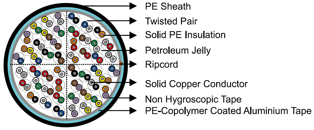
Construction
 |
 |
| Conductors | Solid annealed bare copper, 0.4/0.5/0.63/0.9mm, as per ASTM B-3/class 1 of IEC 60228. |
| Insulation | Solid medium or high density polyethylene as per ASTM D 1248/IEC 60708. |
| Twisted Pairs | Insulated conductors are twisted into pairs with varying lay length to minimize crosstalk. |
| Cabling Element | Twisted Pairs. |
| Cable Core Assembly | Cables of 25 pairs or less are assembled into cylindrical core. Cables larger than 25 pairs are assembled into units, which are then used to form the core. Units are identified by colour coded binders. |
| Core Wrapping | One or more non-hygroscopic polyester tapes are helically or longitudinally laid with an overlap. These tapes furnish thermal, mechanical as well as high dielectric protection between shielding and individual conductors. |
| Moisture Barrier | A layer of corrugated PE copolymer coated aluminium tape (0.2mm/8mil) is applied longitudinally with overlap over the cable core to provide 100% electrical shielding coverage and ensure a barrier against water vapor. |
| Sheath | Black low or medium density polyethylene as per ASTM D 1248/IEC 60708, being able to withstand exposure to sunlight, temperature variations, ground chemicals and other environmental contaminants. |
| Ripcord | Ripcord may be provided for slitting the sheath longitudinally to facilitate its removal. |
| Spare Pairs (optional) | Spare pairs may be provided for large pair cables. |
| Continuity Wire (optional) | One tinned copper drain wire may be longitudinally laid to ensure electrical continuity of the screen. |
Optional Construction
| Self-Support Cables | A 7-strand galvanized steel strand is used as support wire. Black polyethylene sheath covers both core and support wire in a figure-8 construction. |
Abbreviations
Electrical properties
| Nominal Conductor Diameter | mm | 0.4 | 0.5 | 0.63 | 0.9 |
| Conductor Gauge Size | AWG | 26 | 24 | 22 | 19 |
| Maximum Average DC Resistance | Ω/km / Ω/mile | 140/225 | 87/140 | 55/88.6 | 27.0/43.4 |
| Maximum Individual DC Resistance | Ω/km / Ω/mile | 144.2/232 | 89.5/144 | 56.5/91.0 | 28.0/45.0 |
| Minimum Insulation Resistance @500V DC | MΩ.km / MΩ.mile | 1600/1000 | 1600/1000 | 1600/1000 | 1600/1000 |
| Maximum Average Resistance Unbalance | % | 1.5 | 1.5 | 1.5 | 1.5 |
| Maximum Individual Resistance Unbalance | % | 5 | 5 | 5 | 5 |
| Average Mutual Capacitance | nF/km / nF/kft | 48.5-54.0 /14.8-16.5 |
48.5-54.0 /14.8-16.5 |
48.5-54.0 /14.8-16.5 |
48.5-54.0 /14.8-16.5 |
| Maximum Individual Mutual Capacitance | nF/km / nF/kft | 57/17.4 | 57/17.4 | 57/17.4 | 57/17.4 |
| Maximum Individual Capacitance Unbalance pair-to-pair | pF/km / pF/kft | 145/44 | 145/44 | 145/44 | 145/44 |
| Capacitance Unbalance RMS pair-to-pair | pF/km / pF/kft | 45/13.7 | 45/13.7 | 45/13.7 | 45/13.7 |
| Maximum Individual Capacitance Unbalance pair-to-ground | pF/km / pF/kft | 2625/800 | 2625/800 | 2625/800 | 2625/800 |
| Maximum Average Capacitance Unbalance pair-to-ground | pF/km / pF/kft | 574/175 | 574/175 | 574/175 | 574/175 |
| Maximum Conductor Loop Resistance @20°C | Ω/km / Ω/mile | 300/482 | 192/309 | 114/183.6 | 60/96.4 |
| Impedance @1KHz | Ω | 994 | 796 | 660 | 445 |
| Impedance @100KHz | Ω | 147 | 134 | 125 | 122 |
| Impedance @512KHz | Ω | 120 | 118 | 117 | 116 |
| Impedance @1MHz | Ω | 117 | 115 | 114 | 113 |
| Maximum Average Attenuation @0.8KHz | dB/km / dB/kft | 1.64/0.5 | 1.30/0.39 | 1.04/0.32 | 0.74/0.22 |
| Maximum Average Attenuation @1KHz | dB/km / dB/kft | 1.68/0.51 | 1.35/0.41 | 1.08/0.33 | 0.76/0.23 |
| Maximum Average Attenuation @3KHz | dB/km / dB/kft | 3.18/0.97 | 2.52/0.77 | 2.01/0.61 | 1.42/0.43 |
| Maximum Average Attenuation @150KHz | dB/km / dB/kft | 11.4/3.47 | 8.3/2.53 | 6.2/1.89 | 4.4/1.34 |
| Maximum Average Attenuation @772KHz | dB/km / dB/kft | 24.3/7.4 | 19.4/5.9 | 15.4/4.7 | 10.8/3.3 |
| Maximum Average Attenuation @1000KHz | dB/km / dB/kft | 27.1/8.25 | 21.4/6.52 | 17.5/5.33 | 12.8/3.89 |
| Dielectric Strength | |||||
| Conductor to Conductor (3secs) | V DC | 2400 | 3000 | 4000 | 5000 |
| Conductor to Screen (3secs) | V DC | 10000 | 10000 | 10000 | 10000 |
| Minimum EL Far-end Cross-talk-Mean Power Sum | |||||
| @150KHz | dB/305m / dB/kft | 61 | 63 | 63 | 65 |
| @772KHz | dB/305m / dB/kft | 47 | 49 | 49 | 57 |
| @1.6MHz | dB/305m / dB/kft | 41 | 42 | 43 | 44 |
| @3.15MHz | dB/305m / dB/kft | 35 | 37 | 37 | 39 |
| @6.3MHz | dB/305m / dB/kft | 29 | 31 | 31 | 33 |
| Minimum Far-end Cross-talk-Worst Pair Power Sum | |||||
| @150KHz | dB/305m / dB/kft | 57 | 57 | 57 | 59 |
| @772KHz | dB/305m / dB/kft | 43 | 43 | 43 | 45 |
| @1.6MHz | dB/305m / dB/kft | 37 | 37 | 37 | 39 |
| @3.15MHz | dB/305m / dB/kft | 31 | 31 | 31 | 33 |
| @6.3MHz | dB/305m / dB/kft | 25 | 25 | 25 | 27 |
| Minimum Near-end Cross-talk-Mean Power Sum | |||||
| @150KHz | dB/305m / dB/kft | 58 | 58 | 58 | 58 |
| @772KHz | dB/305m / dB/kft | 47 | 47 | 47 | 47 |
| @1.6MHz | dB/305m / dB/kft | 43 | 43 | 43 | 43 |
| @3.15MHz | dB/305m / dB/kft | 38 | 38 | 38 | 38 |
| @6.3MHz | dB/305m / dB/kft | 34 | 34 | 34 | 34 |
| Minimum Near-end Cross-talk-Worst Pair Power Sum | |||||
| @150KHz | dB/305m / dB/kft | 53 | 53 | 53 | 53 |
| @772KHz | dB/305m / dB/kft | 42 | 42 | 42 | 42 |
| @1.6MHz | dB/305m / dB/kft | 38 | 38 | 38 | 38 |
| @3.15MHz | dB/305m / dB/kft | 33 | 33 | 33 | 33 |
| @6.3MHz | dB/305m / dB/kft | 29 | 29 | 29 | 29 |
| Nominal Insulation Thickness | mm | 0.15 | 0.2 | 0.26 | 0.3 |
| Nominal Insulated Conductor Diameter | mm | 0.7 | 0.9 | 1.15 | 1.5 |
Mechanical and thermal properties
Temperature range during operation (fixed state) : -30°C – +70°C
Temperature range during installation (mobile state) : -20°C – +50°C
Minimum bending radius : 10 x Overall Diameter (unarmoured cables) ; 15 x Overall Diameter (armoured cables)
Colour code
Standard colour code is per ICEA S-84-608 given in Colour Code Chart.
Dimensions and weight
Solid PE Insulated & LAP Sheathed Jelly Filled Cables to RUS (REA) PE-39 (ICEA S-84-608)
| Cable Code | Number of Pairs | Nominal Sheath Thickness mm/inch |
Nominal Overall Diameter mm/inch |
Nominal Weight kg/km / lbs/kft |
|---|---|---|---|---|
| 0.4mm Conductor, 0.7mm Insulated Wire | ||||
| TP39-2YF(L)2Y-25P04 | 25 | 1.5/0.059 | 14.0/0.551 | 203/136 |
| TP39-2YF(L)2Y-50P04 | 50 | 1.5/0.059 | 17.1/0.673 | 326/219 |
| TP39-2YF(L)2Y-75P04 | 75 | 1.5/0.059 | 19.5/0.768 | 446/300 |
| TP39-2YF(L)2Y-100P04 | 100 | 1.7/0.067 | 22.0/0.866 | 569/382 |
| TP39-2YF(L)2Y-150P04 | 150 | 1.7/0.059 | 25.7/1.012 | 827/556 |
| TP39-2YF(L)2Y-200P04 | 200 | 1.7/0.067 | 28.7/1.130 | 1023/687 |
| TP39-2YF(L)2Y-300P04 | 300 | 1.8/0.071 | 33.6/1.323 | 1451/975 |
| TP39-2YF(L)2Y-400P04 | 400 | 1.9/0.075 | 37.8/1.488 | 1876/1261 |
| TP39-2YF(L)2Y-600P04 | 600 | 2.0/0.079 | 45.8/1.803 | 2781/1869 |
| TP39-2YF(L)2Y-900P04 | 900 | 2.1/0.083 | 54.7/2.154 | 4057/2726 |
| 0.5mm Conductor, 0.9mm Insulated Wire | ||||
| TP39-2Y(L)2Y-6P05 | 6 | 1.5/0.059 | 11.3/0.445 | 123/83 |
| TP39-2Y(L)2Y-12P05 | 12 | 1.5/0.059 | 13.3/0.524 | 180/121 |
| TP39-2Y(L)2Y-18P05 | 18 | 1.7/0.067 | 14.9/0.587 | 233/157 |
| TP39-2Y(L)2Y-25P05 | 25 | 1.7/0.067 | 16.3/0.642 | 285/192 |
| TP39-2Y(L)2Y-50P05 | 50 | 1.7/0.067 | 20.4/0.803 | 478/321 |
| TP39-2Y(L)2Y-75P05 | 75 | 1.8/0.071 | 23.8/0.937 | 673/452 |
| TP39-2Y(L)2Y-100P05 | 100 | 2.0/0.079 | 27.0/1.063 | 869/584 |
| TP39-2Y(L)2Y-150P05 | 150 | 2.2/0.087 | 31.6/1.244 | 1273/855 |
| TP39-2Y(L)2Y-200P05 | 200 | 2.4/0.094 | 35.4/1.394 | 1579/1061 |
| TP39-2Y(L)2Y-300P05 | 300 | 2.5/0.098 | 42.5/1.673 | 2307/1550 |
| TP39-2Y(L)2Y-400P05 | 400 | 2.5/0.098 | 48.4/1.906 | 3026/2033 |
| TP39-2Y(L)2Y-600P05 | 600 | 2.5/0.098 | 57.9/2.280 | 4429/2976 |
| 0.63mm Conductor, 1.15mm Insulated Wire | ||||
| TP39-2Y(L)2Y-6P063 | 6 | 1.5/0.059 | 12.6/0.496 | 158/106 |
| TP39-2Y(L)2Y-12P063 | 12 | 1.5/0.059 | 15.1/0.594 | 240/161 |
| TP39-2Y(L)2Y-18P063 | 18 | 1.7/0.067 | 17.0/0.669 | 317/213 |
| TP39-2Y(L)2Y-25P063 | 25 | 1.7/0.067 | 18.9/0.744 | 398/267 |
| TP39-2Y(L)2Y-50P063 | 50 | 1.7/0.067 | 24.3/0.957 | 696/468 |
| TP39-2Y(L)2Y-75P063 | 75 | 1.8/0.071 | 28.2/1.110 | 984/661 |
| TP39-2Y(L)2Y-100P063 | 100 | 1.9/0.075 | 32.2/1.268 | 1278/859 |
| TP39-2Y(L)2Y-150P063 | 150 | 2.1/0.083 | 38.0/1.496 | 1898/1275 |
| TP39-2Y(L)2Y-200P063 | 200 | 2.2/0.087 | 43.4/1.709 | 2405/1616 |
| TP39-2Y(L)2Y-300P063 | 300 | 2.2/0.087 | 52.0/2.047 | 3516/2363 |
| TP39-2Y(L)2Y-400P063 | 400 | 2.2/0.087 | 59.2/2.331 | 4614/3100 |
| 0.9mm Conductor, 1.5mm Insulated Wire | ||||
| TP39-2Y(L)2Y-6P09 | 6 | 1.5/0.059 | 15.3/0.602 | 244/164 |
| TP39-2Y(L)2Y-12P09 | 12 | 1.5/0.059 | 18.9/0.744 | 397/267 |
| TP39-2Y(L)2Y-18P09 | 18 | 1.7/0.067 | 21.7/0.854 | 542/364 |
| TP39-2Y(L)2Y-25P09 | 25 | 1.7/0.067 | 24.7/0.972 | 708/476 |